
A CNC machine may have five physical axes without every five-axis program working in the same way. One program indexes the rotary axes, locks the orientation and machines the feature with X, Y and Z. Another changes the tool orientation continuously while the control keeps the programmed tool center point (tool tip) on the programmed path. A third machine has no usable controller-side TCP at all, so the postprocessor must calculate the physical axis coordinates before the program reaches the CNC.
That distinction is fundamental when developing a reliable multi-axis postprocessor. The useful question is not simply “Does the machine have five axes?” It is:
Which transformations are performed by the CAM postprocessor, and which are performed by the CNC control?
Quick summary
- 3+2 machining: the rotary axes position the tool or workpiece first and normally remain stationary during the cutting section.
- Tilted working plane: creates a coordinate system aligned with an inclined surface. Typical functions include FANUC G68.2, HEIDENHAIN PLANE SPATIAL and SINUMERIK CYCLE800.
- TCP / RTCP / TCPM: maintains the programmed tool point while orientation changes. Typical functions include FANUC G43.4/G43.5, HEIDENHAIN FUNCTION TCPM and SINUMERIK TRAORI.
- Without native TCP: a machine-specific postprocessor can sometimes solve the inverse kinematics and write compensated XYZ plus rotary-axis positions directly into the NC program.
- Critical dependency: controller options, OEM commissioning, machine geometry, tool-length handling and safety logic determine which method is valid.
In this article
- What is a CNC working plane?
- What is 3+2 machining?
- G68.2, PLANE SPATIAL and CYCLE800
- Why a working plane is not TCP
- G43.4, TCPM and TRAORI
- Working plane vs TCP comparison
- 5-axis machining without TCP
- Controller vs postprocessor kinematics
- Why machine kinematics matter
- Autodesk Fusion and the postprocessor
- Commissioning checklist
- Frequently asked questions
What is a CNC working plane?
On a conventional 3-axis milling machine, the common G17 configuration uses XY as the machining plane and Z as the tool direction. Programming becomes less direct when the same pocket must be cut on a face tilted by 30 degrees.
Without a coordinate transformation, every point on that pocket must be expressed in the machine’s original coordinate system. With a tilted working plane, the program instead defines a new coordinate system aligned with the inclined surface:
Treat this face as the new XY plane and its normal as the new Z direction.
The pocket can then be programmed with familiar local coordinates even though its physical position is tilted in space. The CNC control or the postprocessor connects that virtual coordinate system to the machine’s actual axes.
Local feature coordinates          Physical machine motion
X0   Y0                            X... Y... Z... B30 C...
X100 Y0            →               X... Y... Z... B30 C...
X100 Y50                           X... Y... Z... B30 C...
X0   Y50                           X... Y... Z... B30 C...
This approach can make programs easier to inspect, makes drilling and pocket cycles more natural on inclined faces and can reduce how much machine-specific coordinate math appears in the NC file. But the exact behavior still depends on controller options and the machine builder’s kinematic commissioning.
What is 3+2 CNC machining?
In 3+2 machining, the rotary axes position the tool or workpiece at a fixed angle before cutting; in simultaneous 5-axis machining, the linear and rotary axes can move together while the tool follows the cutting path.
The term 3+2 describes a five-axis machine used in indexed mode. Consider an XYZBC machine:
- The tool retracts to a verified safe position.
- B and/or C rotate into the required orientation.
- The corresponding working plane or transformed coordinates are established.
- The rotary axes remain fixed.
- X, Y and Z machine the feature.
- The tool retracts before the next index move.
Five axes are available, but only three normally interpolate during that cutting section. This is different from simultaneous 5-axis machining, where linear and rotary axes can change together while the tool is engaged.
Common 3+2 applications include angled drilling, pockets on multiple faces, indexed aggregate machining, mortises on sloped surfaces and trimming features from several fixed orientations.
Working-plane functions by controller
The following commands belong to the same broad concept, but they are not interchangeable. Their syntax, parameters and physical behavior depend on the control generation and OEM machine configuration.
FANUC tilted working plane: G68.2
On supported FANUC systems, G68.2 is associated with Tilted Working Plane functionality. A simplified conceptual sequence can look like this:
G54
G68.2 X0 Y0 Z0 I0 J30 K0
G53.1

G0 X0 Y0 Z100.
G1 Z0 F1000.
G1 X100.

G69
Conceptually, G68.2 defines a transformed coordinate system, G53.1 may orient the tool to that plane on a correctly configured machine, and G69 cancels the coordinate rotation. Production syntax must come from the manuals and proven programs for the actual machine, not from a generic example.
FANUC presents Tilted Working Plane and Tool Center Point Control as distinct five-axis functions. Its own five-axis overview identifies G43.4/G43.5 as TCP functions that can move complex kinematic calculations out of the postprocessor. See FANUC’s official 5-axis machining overview and advanced machining demonstrations.
HEIDENHAIN working planes: PLANE SPATIAL
HEIDENHAIN provides a readable, kinematically independent description of a plane orientation:
PLANE SPATIAL SPA+0 SPB+30 SPC+0 MOVE DIST50 F1000
The program specifies the desired spatial orientation instead of directly prescribing a particular head or table solution. The control can then use its configured kinematics to position the available rotary axes. HEIDENHAIN’s TNC7 documentation describes spatial angles as independent of the physically installed rotary axes. See the official TNC7 basic Programming and Testing manual.
Siemens SINUMERIK working planes: CYCLE800
SINUMERIK uses CYCLE800 to swivel a machining plane on table, head or mixed head/table kinematics. A real call can contain numerous parameters for the swivel data set, orientation mode, retraction and OEM-specific behavior:
CYCLE800(...)
Two machines using SINUMERIK 840D can still require different calls because CYCLE800 is commissioned around the physical machine. Siemens describes this as a static inclined position established before machining the plane; the orientation is not continuously changed during that indexed section. See Siemens’ official manual Milling with SINUMERIK.
A tilted working plane is not TCP
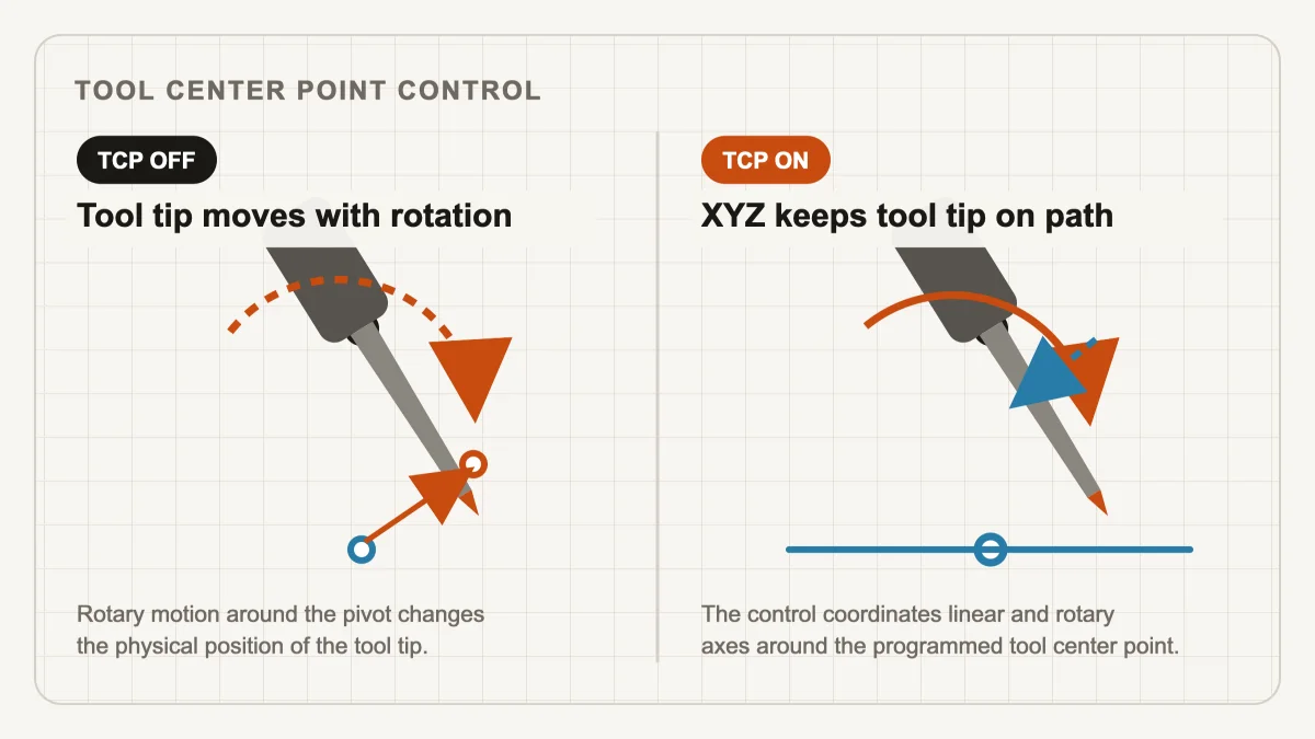
Imagine a 150 mm tool whose tip is exactly on the workpiece. If a rotary head changes from B0 to B30 around its mechanical pivot while X, Y and Z remain stationary, the tool tip moves through an arc. The orientation changed, but the programmed cutting point did not remain fixed.
For indexed work this is normally manageable: retract, rotate, establish the new plane, approach and cut. During simultaneous machining the orientation changes while the cutter is already following the surface. Linear axes must compensate continuously for the displacement caused by the rotary motion.
That is the role of Tool Center Point control.
TCP functions by controller
TCP, RTCP and TCPM are related names used across the industry for tool-point kinematic compensation. The precise definition and programming model vary between control families.
FANUC TCP: G43.4 and G43.5
On suitable FANUC controls, G43.4/G43.5 are commonly associated with Tool Center Point Control:
G43.4 H10
G1 X... Y... Z... B... C... F...
G49
The CNC combines commanded position and orientation with machine kinematics, rotary pivot data and active tool length. FANUC states that these functions can eliminate complex mathematics from the postprocessor and support more machine-independent part programming. Exact activation, cancellation and tool-length rules must still be verified for the target machine.
HEIDENHAIN FUNCTION TCPM
Modern HEIDENHAIN controls provide FUNCTION TCPM; legacy programs may use M128, depending on the control and application.
FUNCTION TCPM F TCP AXIS POS PATHCTRL AXIS
PLANE and TCPM may appear in the same program because they solve different parts of the problem: PLANE defines an orientation or transformed coordinate system, while TCPM governs compensation as orientation changes relative to the programmed contour. Parameters such as F TCP, AXIS POS and path-control mode also affect how the control interprets feed and rotary-axis positions, so a generic one-line substitution is unsafe.
Siemens TCP transformation: TRAORI
On SINUMERIK, the central simultaneous five-axis transformation is activated with:
TRAORI
and commonly deactivated with:
TRAFOOF
With the transformation active, the programmed XYZ position is related to the tool tip and the control compensates for the effect of orientation-axis motion. Siemens explicitly contrasts the fixed orientation of CYCLE800 with the constantly changing orientation enabled by TRAORI in its official five-axis programming manual.
Working plane vs TCP: comparison
| Function | Tilted working plane / 3+2 | TCP / simultaneous 5-axis |
|---|---|---|
| Primary purpose | Machine features in a fixed inclined orientation | Maintain the programmed tool point while orientation changes |
| Rotary axes during the cutting section | Normally stationary | Can move continuously |
| Coordinate concept | Transformed or swiveled working plane | Tool-point and machine-kinematic transformation |
| FANUC | G68.2 | G43.4 / G43.5 |
| HEIDENHAIN | PLANE SPATIAL | FUNCTION TCPM / legacy M128 |
| Siemens SINUMERIK | CYCLE800 | TRAORI |
| Typical work | Angled holes, pockets and contours on fixed faces | Freeform surfaces, swarf cutting and changing tool-axis paths |
| Required transformation | Once per indexed orientation or pre-calculated coordinates | Continuous compensation by the control or pre-calculated output |
The table is a conceptual map, not a programming equivalence chart. Every production implementation must be checked against the exact controller, software options and machine-tool-builder documentation.
What is the difference between G68.2 and G43.4?
FANUC G68.2 transforms or tilts the working coordinate system, while G43.4 activates Tool Center Point Control to compensate the programmed tool center point during multi-axis motion. A 3+2 section may use G68.2 without continuous TCP; a simultaneous section requires continuous kinematic compensation either in the CNC control or in coordinates calculated by the postprocessor.
What is the difference between PLANE SPATIAL and TCPM?
HEIDENHAIN PLANE SPATIAL defines the orientation of a tilted working plane, while FUNCTION TCPM controls tool-point compensation as the tool orientation changes. They solve related but different tasks and can therefore appear together in one program.
What is the difference between CYCLE800 and TRAORI?
CYCLE800 is primarily used to position and transform a tilted machining plane, while TRAORI performs continuous tool-center-point transformation during simultaneous multi-axis motion. The exact parameters and behavior remain dependent on the SINUMERIK version and the machine builder’s commissioning.
What happens on a 5-axis CNC without TCP?
A 5-axis CNC can perform indexed 3+2 machining without continuous controller TCP, and some machines can perform simultaneous motion when a machine-specific postprocessor calculates the required inverse kinematics in advance.
Not every machine with five physical axes has usable native TCP. Common reasons include an older control, an unlicensed option, incomplete OEM commissioning, a proprietary control architecture or a machine originally intended mainly for indexed work.
This does not automatically make every multi-axis operation impossible. The required transformation can sometimes be calculated before the program reaches the CNC.
For each CAM toolpath point, the postprocessor may receive a tool-tip position and tool orientation:
Tool point:       X, Y, Z
Tool direction:   I, J, K
The machine, however, needs physical axis commands:
Machine axes: X, Y, Z, B, C
A machine-specific postprocessor can solve the inverse kinematics, select a valid rotary-axis solution and compensate XYZ for the effect of the head or table rotations.
CAM tool point + tool direction
                 ↓
          inverse kinematics
                 ↓
     machine X Y Z + rotary axes
                 ↓
              NC program
With controller TCP, a conceptual program might contain:
TCP ON
X100 Y50 Z20 B25 C40
X101 Y51 Z19 B26 C41
X102 Y52 Z18 B27 C42
The CNC interprets those commands through its internal kinematic model. Without controller TCP, the postprocessor may emit already-compensated positions:
X93.284 Y47.521 Z31.846 B25 C40
X92.901 Y48.104 Z31.220 B26 C41
X92.447 Y48.761 Z30.517 B27 C42
These values are illustrative only. Their purpose is to show that apparently different XYZ coordinates can represent a similar tool-tip path when the postprocessor has already included the machine geometry.
Who should perform the kinematic transformation?
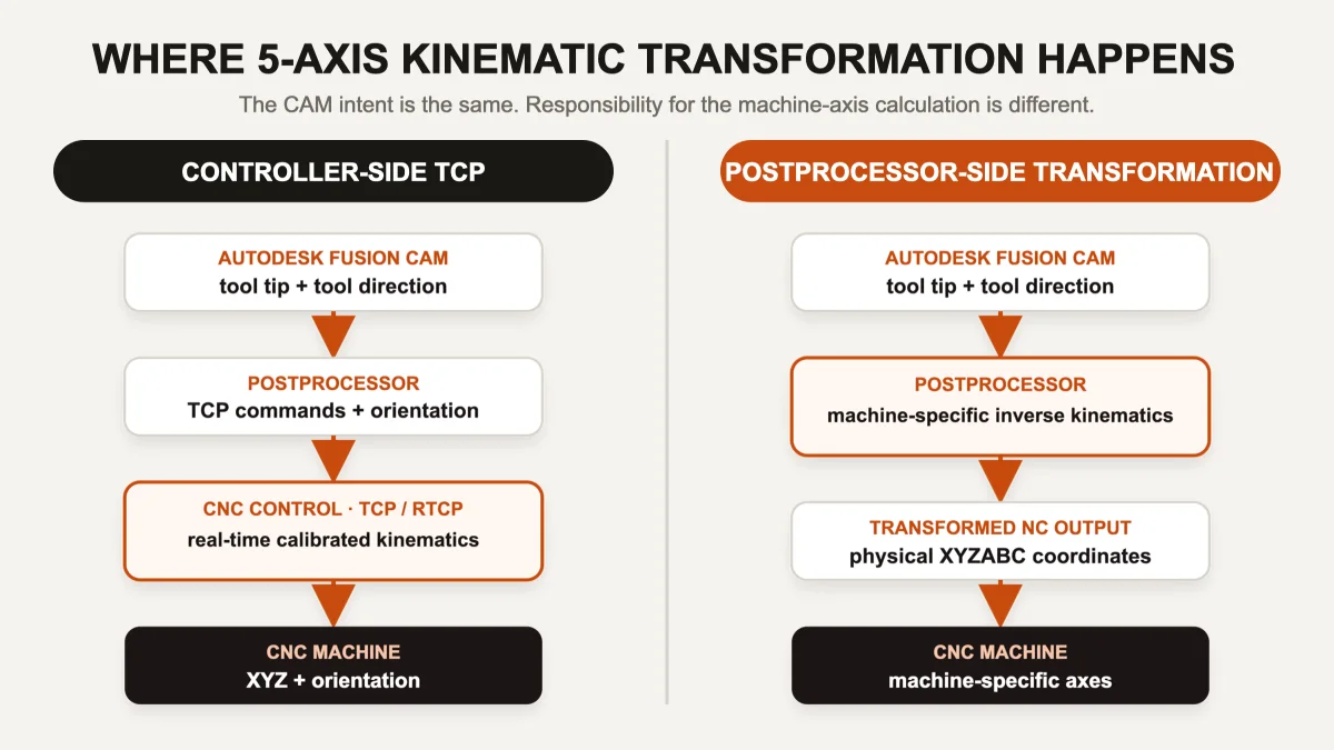
Controller-side TCP uses the CNC’s calibrated kinematic model in real time; postprocessor-side transformation calculates machine-specific XYZ and rotary-axis coordinates before the NC program reaches the control.
Controller-side TCP is usually preferable when it is correctly configured because the control has direct access to the calibrated kinematics, active tool length, work offsets, rotary geometry and interpolation functions. A tool-length change can often remain a tool-table change rather than requiring the NC program to be regenerated.
Postprocessor-side transformation remains valuable for machines whose control cannot provide the required function. The tradeoff is tighter coupling: the program may depend on pivot distances, tool gauge length, workpiece placement, axis directions, rotary limits and the exact machine configuration used during postprocessing.
In practice a postprocessor may use a hybrid strategy:
- controller working-plane transformation for indexed 3+2 sections;
- controller TCP for simultaneous sections;
- postprocessor calculations for safe positioning, axis selection, limits and unwind behavior;
- explicit transformed coordinates where a particular machine function is unavailable.
There is no universal best output independent of the machine.
Unsure whether your five-axis machine should run native TCP or transformed coordinates? A proven NC sample, machine axis diagram and controller option list are often enough to identify the intended architecture before postprocessor development starts.
Discuss your machine configuration →Why machine kinematics matter
Consider three machines that all have five controlled axes:
| Machine topology | What rotates | Kinematic consequence |
|---|---|---|
| XYZ + BC head | Both rotary axes move the tool | Tool length and both head pivots directly affect compensation |
| XYZ + AC table | Both rotary axes move the workpiece | The programmed point must be related to the rotating part and table centers |
| XYZ + B head + C table | One axis moves the tool, one moves the workpiece | The transformation combines both kinematic chains |
The same toolpath can require fundamentally different inverse kinematics on these three machines. Even the same XYZBC label can describe different pivot order, sign conventions and physical rotation centers.
A postprocessor performing the transformation may need accurate values for:
- rotary centers and pivot distances;
- head/table axis order and positive directions;
- tool gauge length and compensation convention;
- machine zero, work offset and setup location;
- axis limits and preferred rotary solution;
- singularity handling, pole behavior and rotary rewinds;
- safe retracts before indexing;
- controller interpolation and feed-rate behavior.
This is why selecting a five-axis postprocessor by controller name or axis letters alone is unsafe. Read what a CNC postprocessor actually controls and our practical guide to Autodesk Fusion postprocessor basics for the broader context.
How Autodesk Fusion and the postprocessor divide the work
Autodesk Fusion does not merely generate a finished list of G-code lines. CAM describes machining intent and tool motion. Depending on the strategy, the postprocessor receives data that can include:
- tool position and orientation;
- section work plane;
- feed rate and spindle state;
- tool and compensation data;
- drilling cycles and operation boundaries;
- multi-axis tool vectors and movement type.
The .cps postprocessor decides how to represent that intent for the target machine. The same Fusion orientation may become:
FANUC:       G68.2 ... / G43.4 ...
HEIDENHAIN:  PLANE SPATIAL ... / FUNCTION TCPM ...
SINUMERIK:   CYCLE800(...) / TRAORI
Legacy CNC:  explicit B... C... X... Y... Z... coordinates
The CAM path can be identical while the final NC programs are entirely different. For machines with limited memory or older controls, there may be further constraints around segmentation, arc fitting and DNC transfer; see Autodesk Fusion for older CNC machines.
For machine-specific options, see the Autodesk Fusion postprocessors available from CCSOFTCZ, including 3-axis, 4-axis, indexed 3+2 and simultaneous 5-axis configurations.
Troubleshooting multi-axis output: separate the three layers
When a tool shifts after an index move or deviates during simultaneous cutting, separate the system into three layers:
- CAM toolpath: What should the cutter do relative to the workpiece?
- Postprocessor: How is that motion represented for this machine and control?
- CNC and machine: How does the controller interpret the commands and move the physical axes?
A machine-side error can originate from any layer. Frequent causes include:
- wrong rotary direction or preferred solution;
- incorrect pivot distance or axis order;
- TCP active when the post assumes it is off;
- TCP inactive when the post assumes it is on;
- incorrect working-plane transformation or cancellation;
- tool length applied twice, or not applied at all;
- a missing controller option;
- OEM-specific behavior behind a nominally standard command.
Separating these layers makes diagnosis faster and prevents compensation from being added in the wrong place.
A practical commissioning checklist
Before releasing a new 3+2 or simultaneous five-axis postprocessor, verify more than syntax.
Documentation and machine definition
- Record the full machine model, serial/configuration variant and controller software version.
- Confirm the physical head/table topology and axis order.
- Obtain kinematic dimensions from approved machine documentation or calibration data.
- Identify licensed and commissioned working-plane/TCP options.
- Collect at least one proven OEM or manually written program for each required mode.
Controlled tests
- Start with air cutting, single-block mode and reduced rapid/feed overrides.
- Test simple known orientations before compound angles.
- Verify the same reference point at several orientations.
- Test tool-length changes deliberately.
- Check positive/negative rotary limits and equivalent orientation solutions.
- Verify cancel/reset behavior after G68.2, PLANE, CYCLE800, TCPM or TRAORI sections.
- Test restart behavior and safe retracts around indexed moves.
Simultaneous motion
- Verify the tool tip, not only the machine axes, in simulation.
- Check feed interpretation when rotary motion dominates.
- Test near singularities and rotary discontinuities.
- Confirm rewind/unwind moves are collision-safe.
- Validate the output on representative geometry before production release.
Conclusion
Working-plane transformations and TCP are related, but they solve different problems.
Tilted working plane              Tool center point control
FANUC G68.2                       FANUC G43.4 / G43.5
HEIDENHAIN PLANE SPATIAL          HEIDENHAIN FUNCTION TCPM
SINUMERIK CYCLE800                SINUMERIK TRAORI
A working-plane function lets the program describe geometry in a fixed inclined coordinate system. TCP continuously compensates the programmed tool point while orientation changes. When the controller cannot provide one of these transformations, a correctly developed postprocessor may calculate some or all of the required kinematics and output machine-specific coordinates directly.
The decisive questions are therefore:
- Which transformations does the controller support?
- Which functions are licensed and correctly commissioned by the machine builder?
- Which calculations must be performed by the postprocessor?
- Which tool, offset and machine data remain variable at runtime?
Those answers determine whether a multi-axis CAM toolpath becomes a safe, predictable NC program.
