
A touch probe makes setup easier, but work zero can be found without one. You need a known reference, a suitable aid and a clear idea of which coordinate you are setting.
The biggest problem is usually not the touch itself. It is the forgotten distance between the tool axis and the edge, or confusing work zero with tool length.
Quick summary
- Three different values: machine zero, work zero (G54, G55…) and tool length offset. They are not interchangeable.
- X and Y: a mechanical edge finder with a known diameter. When the edge is found, the spindle axis is offset by its radius.
- Z: touch off over paper, a feeler gauge or a gauge block. The tool tip sits above the surface by the gauge thickness.
- Woodworking CNC: decide whether Z = 0 is the top or the bottom face and check stops, vacuum pods and the spoilboard.
- Autodesk Fusion: the Setup origin must match the point set on the machine, and the postprocessor must pass it through correctly.
In this article
Three values you must keep apart
Machine zero is the reference of the machine coordinate system. Homing establishes the relationship between the machine position and this reference; on its own it does not determine where the workpiece is.
Work zero is the program origin relative to the workpiece. Controls programmed in ISO code commonly use a work coordinate system such as G54 or G55. The offset lets you use part coordinates regardless of where the part sits on the table.
Tool length offset describes the length of the tool relative to the chosen reference. Two tools with the same program origin can have different length offsets. Work zero and the tool table must therefore not be mixed up. We cover offsets in more detail in Tool compensation in Autodesk Fusion.
This article explains the principle for 3-axis milling. How values are entered, how offsets are activated and how setup mode works is defined by the manual of your specific machine.
X and Y: find the edge and account for the radius
A mechanical edge finder is well suited to setting X and Y by hand. Its contact tip has a known diameter and it signals the edge position on contact. At the moment the edge is found, however, the spindle axis is not on the edge: it is offset from it by the radius of the contact tip.
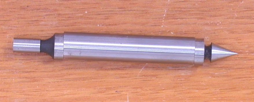
Practical procedure
- Clean the reference edge and clamp the part. Use a face that matches the program origin and is not rounded, chipped or burred.
- Clamp the edge finder and set the speed recommended by its manufacturer. A rotating mechanical edge finder is not meant for normal cutting speeds; manufacturers typically specify around 400–600 rpm. If the spindle cannot run that slowly (typical for high-speed electro-spindles on woodworking machines), use a different aid.
- Approach the edge in setup mode in small increments. Capture the moment the edge is found as described in the tool’s instructions. Repeat the measurement to confirm it is repeatable.
- Store the work offset, accounting for the radius. Repeat for the second axis. Move away from the part before travelling to another side.
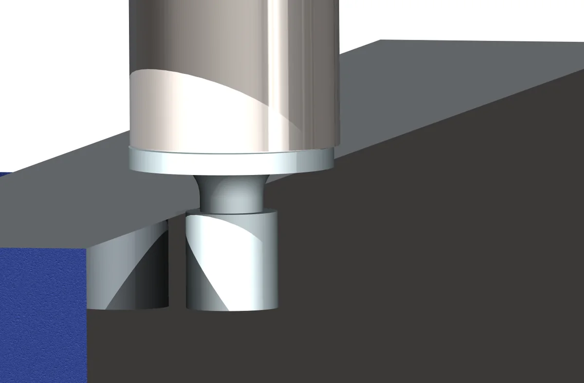
Without an edge finder, you can roughly locate an edge with a stationary tool and a gauge, accounting for the radius of the actual contact surface and the gauge thickness. Cutting edges, runout and an uneven edge reduce repeatability, so use a proper measuring aid for accurate work.
Z: paper, feeler gauge or gauge block
Height can be set by bringing the tool tip to the reference surface by hand over a material of known thickness. The paper method also appears in the Haas manual for manual tool setting. It is accessible, but the result depends on the paper thickness and on feel.
Touching off on the top face
Clean the surface and the gauge. With the spindle stopped, position the tool over the measuring point and reduce the jog increment. Keep the gauge under the tool and lower Z gently until you feel a light, repeatable drag as you slide it. Do not press the tool into the material and never hold the gauge near a rotating cutter.
When touching off over a gauge, the tip is not on the surface. It sits above it by the gauge thickness. Account for this difference using the work-offset or tool-setting function, depending on the control procedure you use. After storing the value, move the tool away and verify the result.
Where does the value go?
If tool lengths are already measured correctly and their offsets are active, this procedure locates the reference surface in the work coordinate system. If you are only now measuring the tool length, you update the corresponding entry in the tool table. LinuxCNC, for example, lets you enter the gauge dimension directly into the tool table when touching off.
After changing a manually clamped tool, the new length must be taken into account. Either measure the tool into the table or use your approved procedure for re-setting Z.
Woodworking CNC: zero on top, at the bottom or from stops?
For panel and solid-wood parts it helps to decide whether Z = 0 is the top face or the bottom face of the part. The choice must match the program, the real thickness and the clamping method. Likewise, distinguish the bottom of the part from the machine table: vacuum pods, consoles or a fixture may sit between them.
| Z reference | 18 mm panel, +Z up |
|---|---|
| Top face of the part | Top face: Z = 0 Bottom face: Z = -18 mm A 5 mm deep pocket has its floor at Z = -5 mm |
| Bottom face of the part | Bottom face: Z = 0 Top face: Z = +18 mm A 5 mm deep pocket has its floor at Z = +13 mm |
These numbers describe the geometry of the same pocket with two different origins. They do not mean the values can be copied directly into every woodworking format: a particular control may express depth differently. More on woodworking specifics in Autodesk Fusion in the woodworking industry.
Repeated loading against stops
If the machine or fixture provides verified stop positions, X and Y can be derived from them without finding edges at every load. The active work area, the stop used and the part orientation must match, though. Chips between the part and the stop or incorrect seating shift the part even though the stored values stay the same.
On a console table, include the height of the supports and vacuum pods in the check. On a nesting table, check the spoilboard surface. Re-verify the height reference after changing a fixture or surfacing the spoilboard. Entering the material thickness alone does not replace checking the real position of the part.
How to set it in Autodesk Fusion
In Manufacture > Setup, set the work axis orientation and the Origin. Stock box point selects a point on the stock bounding box; Model box point a point on the model bounding box. Selected point lets you pick a specific reference point. Z should point away from the machined face.
If you touch off a stock corner by hand, choose the matching stock corner in Fusion. If the model has stock allowance, its corner may be somewhere else. If you set zero on the rough blank but CAM works from the finished part, the difference ends up in the machining.
The postprocessor must preserve the intended reference. The generated program has to use the matching work coordinate system or origin definition of the machine. A correct Fusion setup is one half; correct interpretation on the CNC is the other. How the postprocessor handles this is explained in What is a postprocessor in CAM software.
Check your postprocessor output →Verify before the first cut
Before machining, verify the program position against the real part and clamping. Use the verification mode your machine offers, single block and a suitable speed limit. Do not rely on reducing the feed override alone: rapid traverse may have a separate override.
Five-point check
- The active origin on the machine matches the program and the CAM setup.
- The X, Y and Z directions match the part orientation.
- The edge finder radius and gauge thickness are accounted for.
- The correct tool is in the spindle and the control uses its correct length.
- Safe heights clear the highest obstacle, including clamps.
When travelling between measured edges, first raise the tool to a safe height.
A clear setup sheet with the origin and tools marked also helps on the shop floor, for example one from Setup Sheet Studio for Autodesk Fusion.
When to look at the setup and when at the postprocessor
If the whole program shows the same offset, check the work origin, active offsets and clamping first. If the problem appears after a tool change, check the tool length and how the program uses it. The postprocessor output can also be at fault, but without checking these values the cause cannot be determined reliably.
