
Designing a staircase as a 3D model is one part of the job. Preparing individual parts, joinery, manufacturing drawings and machining is another. When these steps are handled separately, every dimensional change creates additional manual work and more relationships to check.
Fusion Stair Designer connects parametric timber-stair design with manufacturing outputs directly in Autodesk Fusion. This article follows an L-shaped staircase with a landing from input dimensions through construction and checks to machining preparation. For the wider context, see Autodesk Fusion for woodworking CNC.
Quick summary
- One source of definition: dimensions and construction choices are stored in the parametric stair definition.
- Manufacturing outputs: the definition can produce a review PDF, individual-part DXFs, CSV data and other production files.
- Manual CAD changes: STEP uses the current Fusion bodies; calculated PDF, DXF, CSV and CAM outputs use the saved parametric definition.
- CAM: Design + CAM prepares supported three-axis setups, 2D Contour and 2D Pocket operations; the result must be verified for the actual machine and workholding.
- Scope of checks: the add-in does not approve structural capacity, headroom, building-code compliance or physical assembly.
In this article
1. Define the requirements before modelling
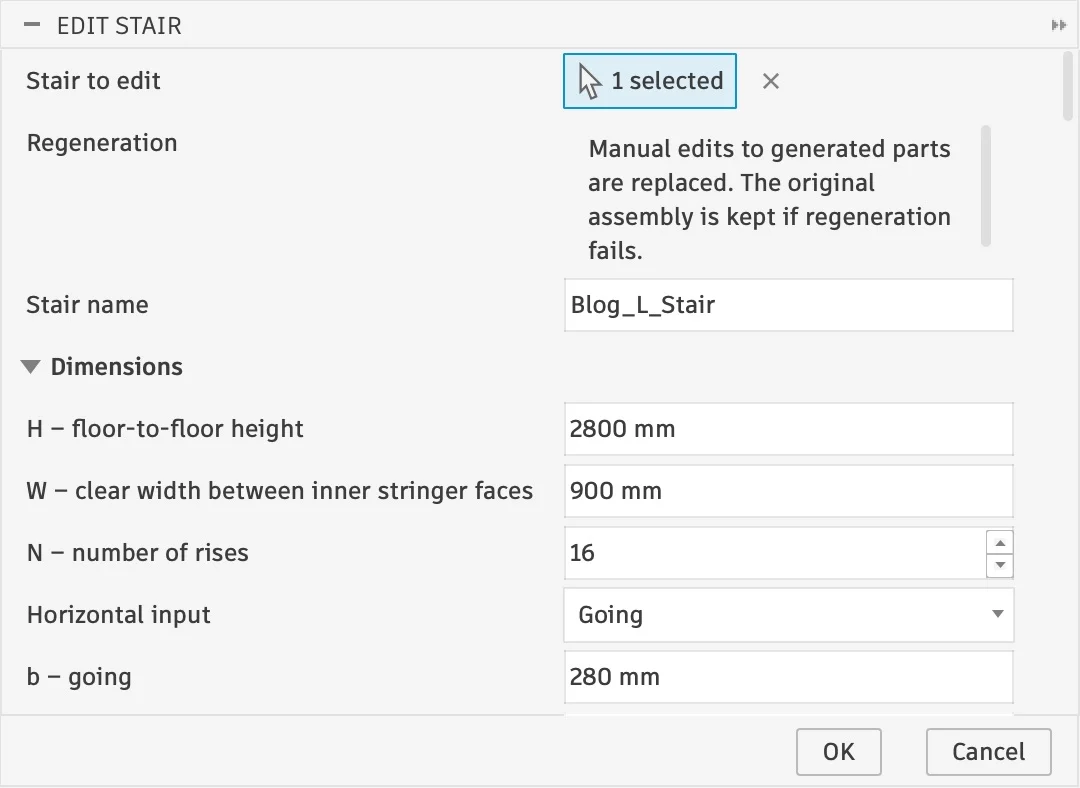
Before modelling, you need the floor-to-floor height, available plan space, stair width and required layout. An L-shaped staircase also requires the position and dimensions of the landing.
Construction choices matter too: tread and stringer thickness, whether risers are used, how the treads are supported and how the guardrail is built. These inputs affect both geometry and subsequent manufacturing.
Fusion Stair Designer stores the settings in a parametric stair definition. The model is therefore created from one shared definition that can be reopened and edited.
2. Create the parametric assembly
The entered parameters generate a Fusion assembly containing treads, optional risers, stringers, a landing and guardrail components according to the selected configuration.
You can reopen the parameters, change dimensions and regenerate the assembly. After a change, check the model and recreate the related manufacturing outputs.
The add-in supports straight stairs and L-shaped stairs with a landing. For U-shaped winder stairs, it creates real geometry for the stair, supports, curved structures and guardrails, but the feature remains a technology preview. Its outputs are marked incomplete because structural capacity, complete guardrail joinery, headroom, regulations and physical assembly have not been verified.
3. Design stringers and joints
An external stair shape is not enough for manufacturing. You also need to define how the parts fit together.
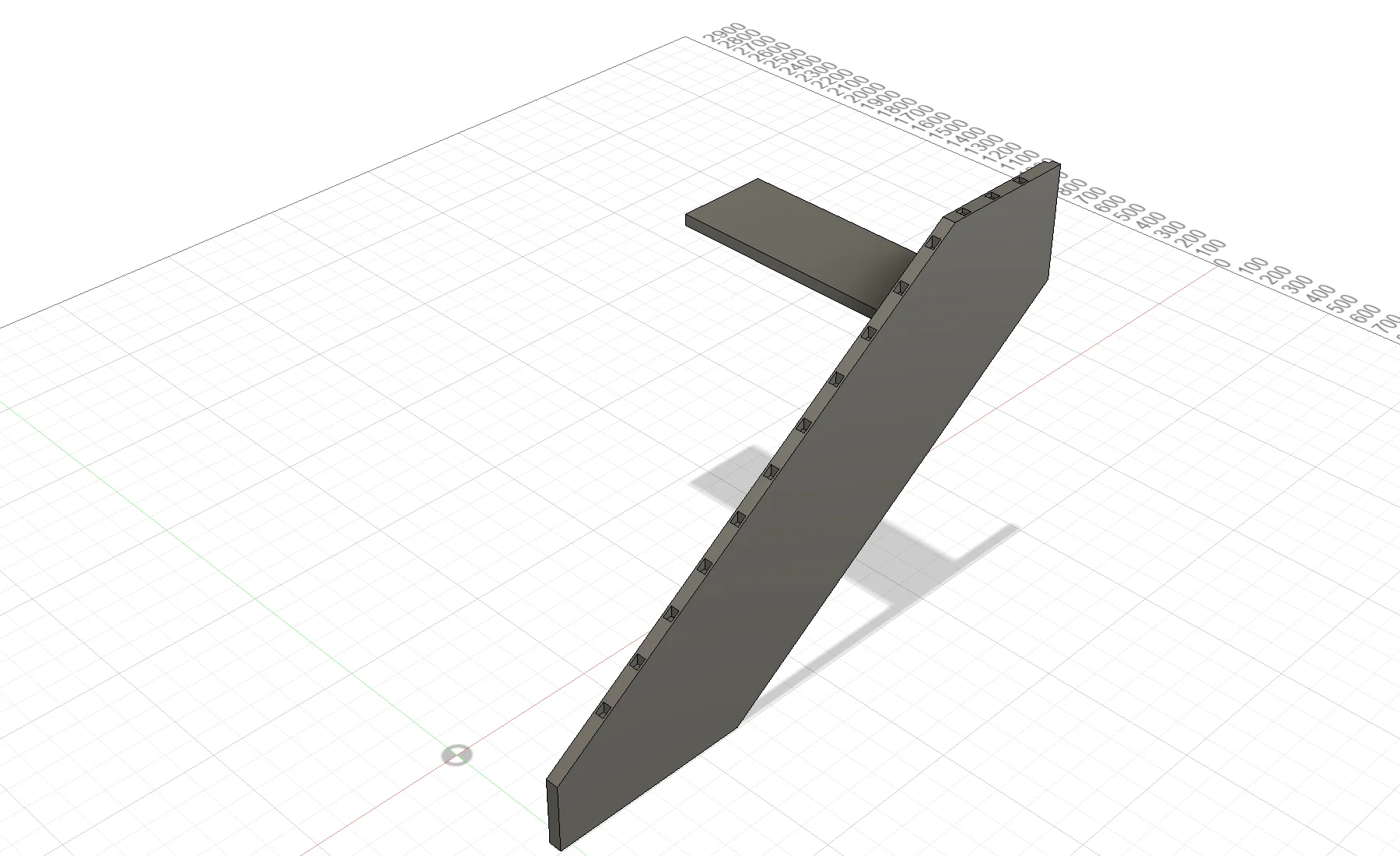
The add-in can configure housed treads in stringers, cut stringers or a mixture of the two on opposite sides. Depending on the configuration, joints can use full tread-end housing, a tenon or a wedged arrangement.
Joint clearances and internal-corner reliefs can be based on the cutter diameter. This is especially important for pockets: a rotary cutter cannot produce the same internal corner as the sharp corner of a mating part.
Before production, check every joint against the material, tools and assembly method. For a new construction detail, test the selected joint on a sample part.
4. Check the design before export
Check Stair helps identify implemented geometric issues, design warnings and missing manufacturing information.
The check can cover dimensions, thicknesses, part seating, pockets and remaining material. It also separates areas that the add-in does not assess.
A successful check is therefore not a structural report or confirmation of building-code compliance. It is an input for further design review and manufacturing preparation.
5. Manufacturing documents and parts
The parametric definition can generate a manufacturing package for a specific stair revision. Depending on the selected outputs, it can include:
- an assembly DXF and separate DXFs for individual parts;
- project and part documentation in PDF;
- a CSV bill of materials with manufacturing data;
- stored parameters and revision information.
STEP export provides 3D geometry for another CAD/CAM system.
It is important to understand the source of each output. Calculated PDF, DXF, CSV and CAM outputs use the saved parametric definition. Manual changes to Fusion bodies do not automatically carry over to them. STEP, by contrast, exports the current bodies and can therefore include disclosed manual changes.
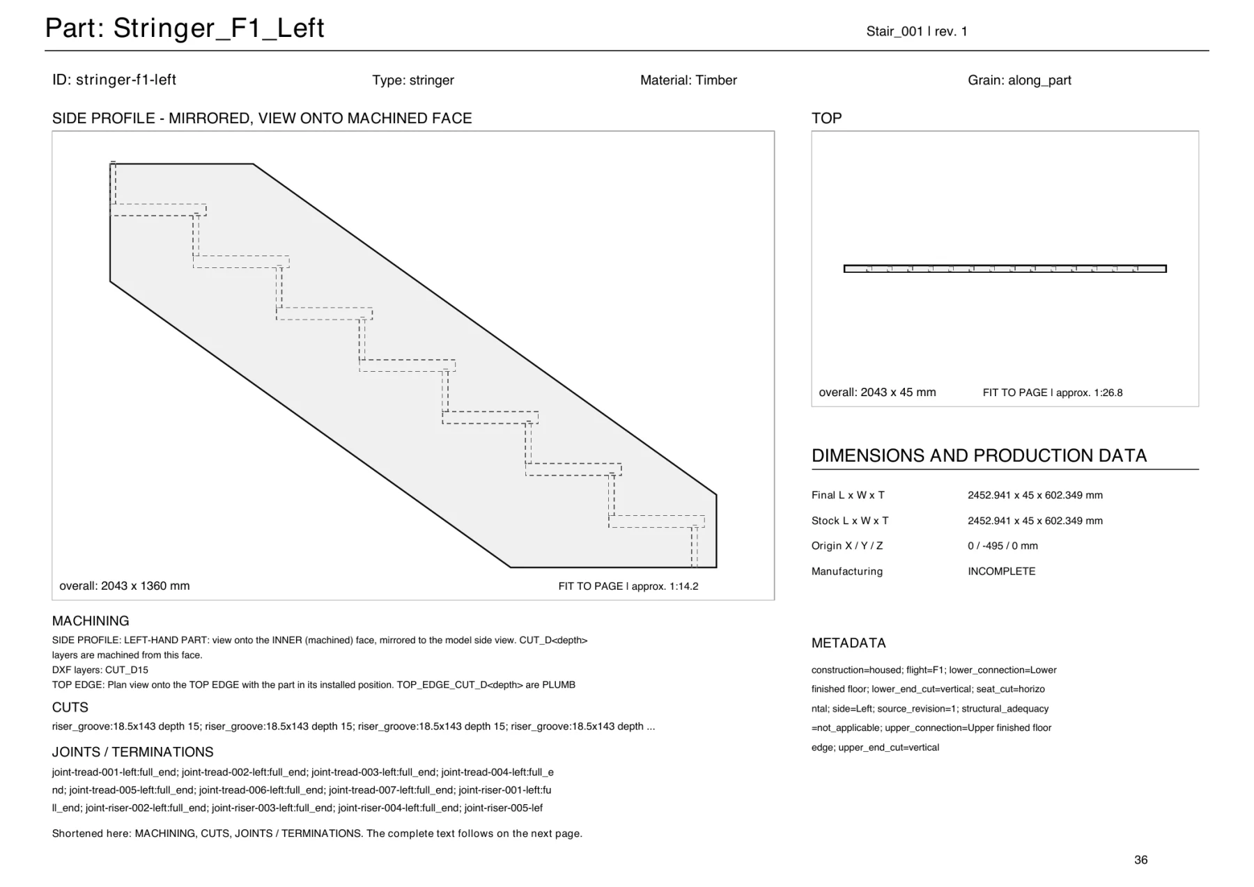
You can review the documentation structure and scope in the Fusion Stair Designer sample PDF report.
6. Prepare machining in Fusion CAM
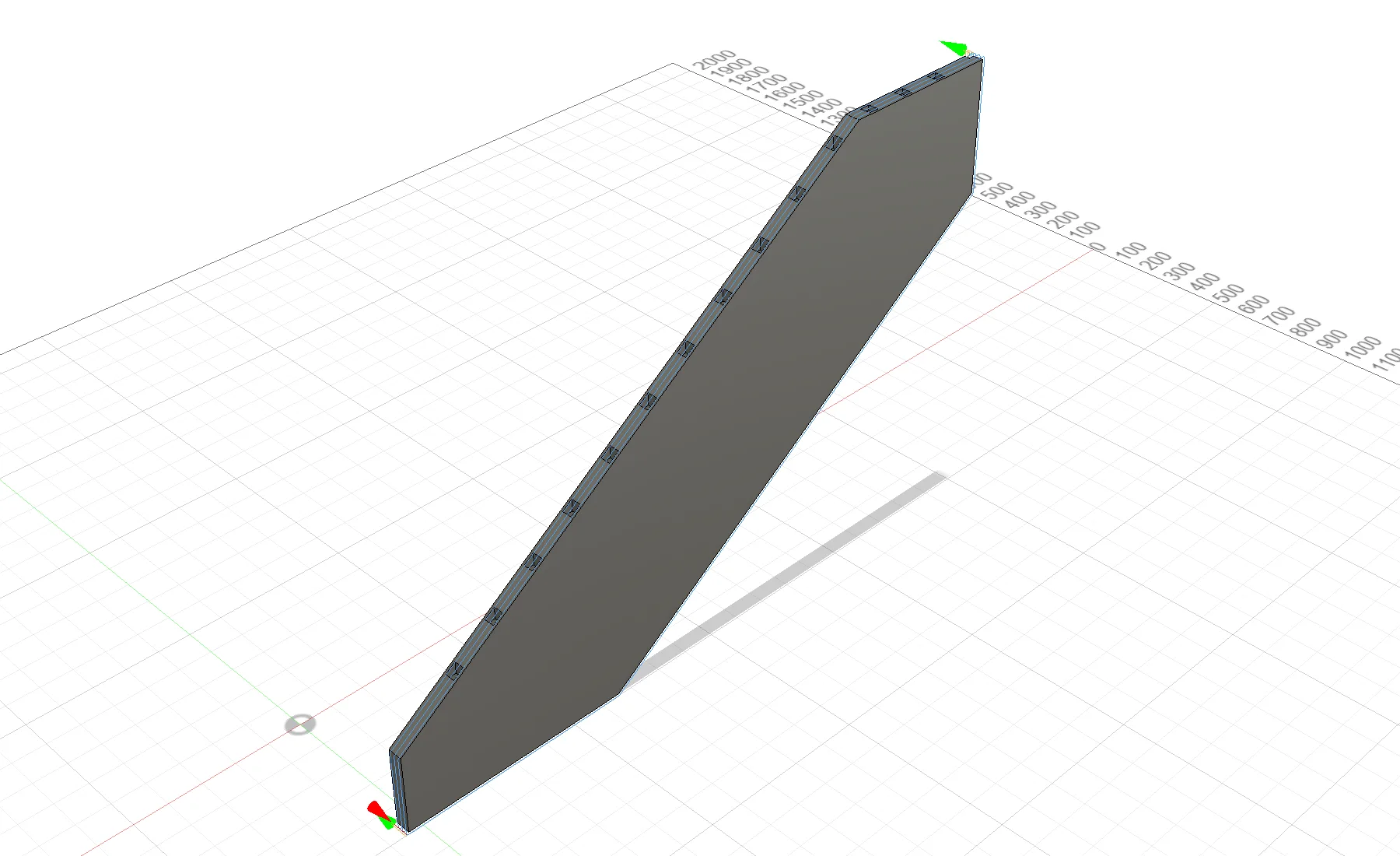
The Design + CAM edition continues from the design by creating supported three-axis setups and operations in Fusion Manufacture. It uses 2D Contour and 2D Pocket operations and starts toolpath generation.
Each setup has its own orientation, stock and work origin. Machining the top, bottom or side can require separate workholding. An automatically created setup does not solve the physical location and clamping of the part on the machine.
Unsupported operations remain listed for manual planning. Before machining, verify tools, cutting data, workholding, toolpaths and the resulting NC program.
Output for a specific CNC requires a suitable post processor, which is not included with the add-in. Create / Update CAM prepares one NC Program per setup; it writes an NC file only when posting is enabled, the generated toolpaths are valid and a suitable post processor is selected.
When this workflow makes sense
Fusion Stair Designer is intended for users who want to design timber staircases in Autodesk Fusion and create manufacturing data from one shared parametric definition.
The Design edition covers design plus documentation and geometry export. Design + CAM adds automated preparation of supported machining in Fusion.
Before buying, test your own construction, joints and required outputs. The three-day trial also includes CAM.
Try Fusion Stair Designer on your own project. Review the current features, limitations and installers on the product page.
View features and download the trial →Need to connect the output to a specific CNC machine? See the Autodesk Fusion post processors.
