
A conventional CNC program tells the machine exactly where to move. That is ideal for most CAM-generated toolpaths. But some production tasks are not simply a fixed list of coordinates: a hole pattern changes with part size, a probe must react to a measured value, or a special aggregate always needs the same machine sequence.
FANUC Custom Macro—often called Macro B—adds variables, calculations, conditions, loops and parameterized calls to the CNC programming language. One tested routine can therefore handle a family of similar tasks instead of duplicating the same NC blocks in every program.
Quick summary
- Variables: store dimensions, counters, measured values and calculated positions.
- Logic: IF conditions and WHILE loops let a program validate inputs and repeat operations.
- G65: calls a macro program and passes arguments into defined local variables.
- Best division of work: CAM handles part geometry; macros often handle stable, machine-specific behavior.
- Safety: every macro must be validated against the exact control, installed options and machine-builder implementation.
In this article
What is FANUC Macro B?
A normal CNC block contains fixed values:
G0 X100. Y50.
G1 Z-10. F1000.
A macro can store those values in variables and use the variables in address words:
#100 = 100.
#101 = 50.
#102 = -10.

G0 X#100 Y#101
G1 Z#102 F1000.
The physical motion can be identical. The difference is that the values can now be passed into the routine, calculated, checked or reused. FANUC describes Custom Macro as an extension of the part-programming language with program-flow control, mathematical and logical functions, and local and system variables. The option is intended for applications such as custom cycles, parametric families, probing and error-proofing. See the official FANUC CNC options overview.
Macro B is therefore not a replacement for G-code. It is a way to make selected parts of a G-code program parametric and reusable.
Variables turn fixed code into a reusable routine
The # character identifies a macro variable:
#100 = 50.
#101 = #100 + 20.
After the second block, #101 contains 70. Variables can be used for positions, dimensions, feeds, counters and intermediate calculations.
Three broad categories matter in practice:
| Variable type | Typical purpose | Important consideration |
|---|---|---|
| Local variables | Arguments and temporary values inside a called macro | Normally belong to the current call level |
| Common variables | Values shared between programs | Available ranges and whether values survive power-off depend on the control/options |
| System variables | CNC data such as supported offsets, positions, alarms or interface states | Meanings and write access are control- and OEM-specific |
The category matters. A temporary calculation should not silently overwrite a persistent production value, and a machine-interface variable must never be guessed from a program written for another machine.
Conditions, loops and custom alarms
Variables become much more useful when the macro can make decisions. A simple input check can reject an impossible value before any cutting motion begins:
IF [#1 LT 1] THEN #3000 = 1 (INVALID HOLE COUNT)
IF [#2 LE 0] THEN #3000 = 2 (INVALID PITCH)
On commonly configured Macro B systems, writing an appropriate value to #3000 generates a user alarm and stops execution. The actual alarm behavior and supported system variables must be verified in the manual for the target control.
A loop can then repeat an operation:
#100 = 0
WHILE [#100 LT #1] DO1
  (MACHINING BLOCKS)
  #100 = #100 + 1
END1
The CNC repeats the blocks between DO1 and END1 until the counter reaches the requested quantity. This is useful for rows of holes, bolt circles, repeated measurements and standard production cycles.
FANUC’s own Custom Macro training covers variables, the G65 simple call, arithmetic, WHILE, IF and system variables as the core progression. Its examples include custom drilling and pocket cycles, automatic tool-length measurement and argument validation. See the official FANUC Custom Macro course description.
How a G65 macro call works
G65 is the common non-modal macro call:
G65 P9010 X100. Y50. Z15. A8. B32. F500.
This block says: run program O9010 and pass it a set of arguments. In the common simple-call argument assignment, the words are mapped to local variables such as:
| Call word | Local variable | Meaning in this example |
|---|---|---|
A8. | #1 | number of holes |
B32. | #2 | pitch in mm |
F500. | #9 | drilling feed |
X100. | #24 | first-hole X position |
Y50. | #25 | row Y position |
Z15. | #26 | positive depth value used by this macro |
The meaning in the last column is an interface designed by the macro author. FANUC defines the argument-to-variable assignment; the machine project defines whether A means quantity, angle or something else.
P9010 identifies O9010; it is not a value available to the macro as an ordinary machining argument. Other call formats, repeated I/J/K argument sets, modal macro calls and custom G- or M-code mappings exist, but their use should follow the exact FANUC and machine-builder documentation.
A practical hole-row example
Without a macro, ten holes at a 32 mm pitch may be output as ten separate positions. That is valid, transparent NC code. But if the same machine-side drilling routine is used by many products, a parameterized interface can be cleaner.
Conceptually, the postprocessor writes:
(8 HOLES, 32 MM PITCH, START X100 Y50, DEPTH 15)
G65 P9010 X100. Y50. Z15. A8. B32. F500.
The macro can then validate the call and calculate every position:
O9010 (HOLE ROW - CONCEPTUAL EXAMPLE)

IF [#1 LT 1] THEN #3000 = 1 (INVALID HOLE COUNT)
IF [#2 LE 0] THEN #3000 = 2 (INVALID PITCH)
IF [#26 LE 0] THEN #3000 = 3 (INVALID DEPTH)

#100 = FIX[#1]
#101 = 0

WHILE [#101 LT #100] DO1
  G0 X[#24 + #101 * #2] Y#25
  (CALL THE MACHINE'S VERIFIED DRILLING SEQUENCE HERE)
  #101 = #101 + 1
END1

M99
This example deliberately leaves the actual drilling motion as a comment. Retraction levels, spindle state, canned-cycle behavior, units, active plane, tool-length compensation and safe motion must be defined for the real machine. Generic internet code should never become a production drilling cycle without that engineering work.
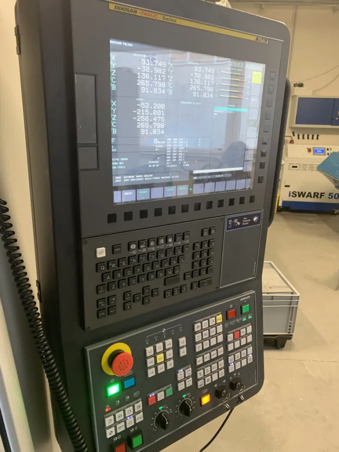
FANUC macros as a bridge between CAM and the machine
The most useful macros are often not typed manually for every job. They are called automatically by a CAM postprocessor.
Autodesk Fusion operation
            ↓
Machine-specific postprocessor
            ↓
Validated G65 call and arguments
            ↓
FANUC Macro B routine
            ↓
Machine-specific action
Autodesk Fusion owns the part geometry and manufacturing intent. The postprocessor recognizes the relevant operation and translates it into the agreed machine interface. The macro executes the stable machine-side sequence.
For example, a Fusion operation or custom operation property can describe a special drilling head. Instead of outputting a long sequence of hardware-specific blocks every time, the postprocessor may output one validated macro call. If the machine builder later changes the internal activation sequence, the macro can be revised and re-qualified while the CAM-side interface remains stable.
FANUC itself shows this modular approach in an official five-axis workflow, where G65 calls activate, measure and deactivate standardized machine functions around the part geometry. See FANUC’s 5-Axis Part-Centric Workflow.
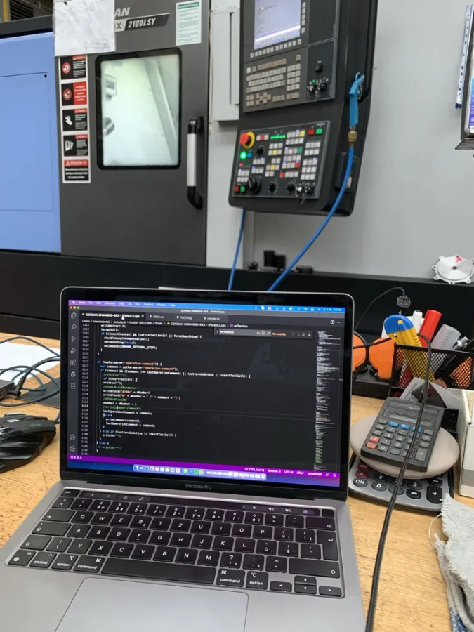
What should stay in CAM?
Macros are powerful, but moving every calculation into the control makes a system harder to simulate and maintain.
A useful division is:
| Primarily part geometry | Primarily machine behavior |
|---|---|
| 3D surface toolpaths | Probe and measurement sequence |
| Adaptive roughing | Special aggregate activation |
| Collision-aware linking moves | Fixture or pallet selection |
| Simultaneous multi-axis tool orientation | Standard OEM startup/shutdown sequence |
| Rest machining | Reusable machine-specific drilling head cycle |
Complex toolpath geometry normally belongs in CAM, where it can be calculated, visualized and simulated. Stable behavior that belongs to the physical machine can be a good macro responsibility. The postprocessor is the contract between those two layers.
Good real-world macro applications
Common applications include:
- probing and automatic work-offset updates,
- tool measurement and wear checks,
- hole rows and bolt-hole circles,
- special drilling heads or angle aggregates,
- fixture, pallet or vacuum-zone selection,
- repeated inspection or measurement,
- controlled access to machine-builder sequences,
- parametric families of simple parts.
The best candidates have clear inputs, predictable outputs and a sequence that is reused often enough to justify centralized testing.
Safety and commissioning
A macro error can command real motion. Good macro development therefore includes more than correct syntax.
- Define every argument, unit, sign and permitted range.
- Reject missing, zero, negative or excessive values before motion.
- Establish required modal states explicitly where safe and appropriate.
- Separate calculation from machine motion so values can be inspected.
- Test without a part or cutting load first.
- Use simulation, graphics, machine lock or dry-run functions when the specific machine permits it.
- Run the first physical test in single block with reduced rapid and feed overrides.
- Verify tools, offsets, fixtures, retract planes and restart behavior.
- Save the proven macro, parameters and related postprocessor as one versioned release.
Custom alarms should tell the operator what is wrong, not merely that the routine stopped. INVALID PITCH is more useful than an unexplained downstream overtravel.
Why the same macro may not work on another machine
Two machines with FANUC controls can still differ in:
- CNC series and software generation,
- Custom Macro option availability,
- local/common/system variable support,
- protected
O9000program settings, - machine-builder parameters and PMC logic,
- custom G-code and M-code mappings,
- axis names, units and active modal assumptions,
- safety interlocks and peripheral hardware.
That is why a proven macro is machine-specific until the second machine has been reviewed and tested. The FANUC function catalog also notes that functions can require particular hardware, CPU, memory or compatible options; the relevant manuals and original manufacturer documentation prevail.
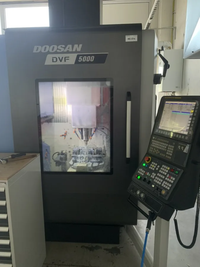
A maintainable macro interface
Treat a production macro like a small machine API:
- give it a stable program number and documented purpose,
- define every argument and its local-variable mapping,
- specify units, sign conventions, defaults and valid ranges,
- document which modal states the caller must establish,
- state which offsets or system variables the macro reads or changes,
- return the machine to a documented state,
- version the macro together with the matching postprocessor,
- keep a short acceptance test with known inputs and expected results.
This discipline is what turns G65 P9010 ... from a mysterious shortcut into a reliable interface between Autodesk Fusion, the postprocessor and the CNC machine.
Conclusion
FANUC Macro B is a practical tool for reusable CNC logic. Variables make fixed values configurable, conditions prevent invalid operation, loops remove repeated blocks, and G65 provides a compact interface for passing parameters into a tested routine.
The goal is not to hide every toolpath inside the control. It is to put each responsibility in the right place: geometry in CAM, translation in the postprocessor and stable machine behavior in a carefully designed macro where that makes the integration simpler.
At CCSOFTCZ, we develop custom Autodesk Fusion postprocessors and CNC integrations for FANUC and other industrial controls. Depending on the machine, the right output may be conventional G-code, a controller function, a machine-builder cycle or a coordinated combination of postprocessor logic and Macro B. For related examples, see our FANUC FOCAS automation case study and the guide to 3+2 versus simultaneous 5-axis CNC machining.
